
Project Overview
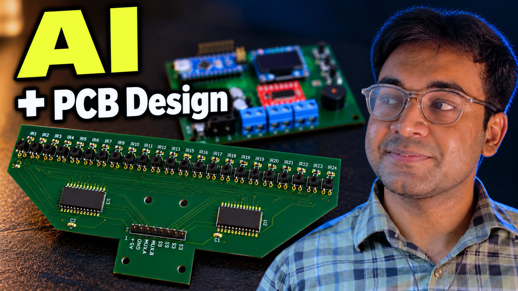
This project is a custom line follower robot built around two main electronics boards:
A 24-channel line follower sensor board
A custom line follower robot mainboard
The sensor board is the main focus of this project. Instead of using ready-made line sensors, I designed the complete electrical circuit around the QRE113 reflectance sensor and created a custom PCB for the sensor array.
The mainboard handles the robot's controller, motor driver, power system, display, and user controls.
Loads from YouTube when you press play, and YouTube may then set cookies. Watch on YouTube
1. The Line Follower Sensor Board
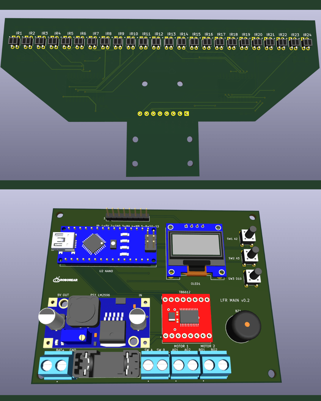
The sensor board is responsible for detecting the line underneath the robot.
The board uses 24 QRE113 infrared reflectance sensors arranged across the front of the robot. The goal was to create a compact sensor array with enough sensing points to accurately determine the position of a line.
The most important part of this board was not the PCB layout—it was the electrical schematic.
1.1 Why the QRE113?
The QRE113 combines two components in one package:
An infrared LED
A phototransistor
The infrared LED illuminates the surface below the robot. The phototransistor responds to the amount of infrared light reflected back from that surface.
A lighter surface generally reflects more infrared light than a darker line. The circuit converts this difference into an electrical signal that can be read by the robot.
2. The QRE113 Sensor Circuit
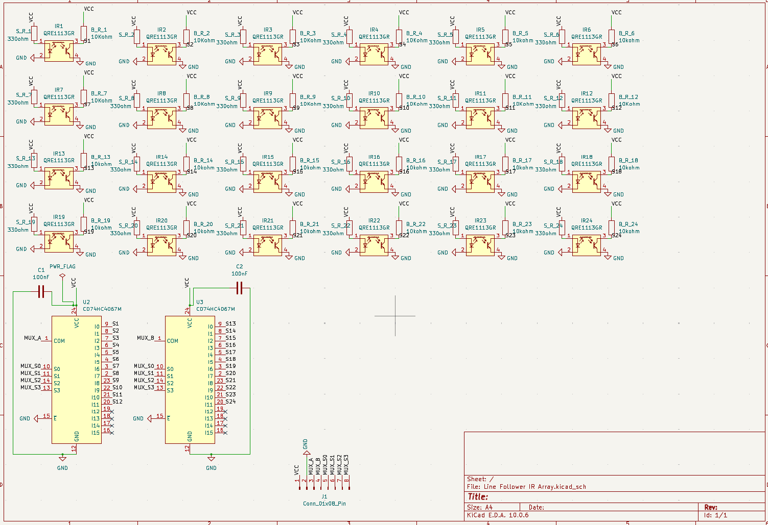
This is the most important section of the article.
Rather than simply showing the schematic, explain it in small blocks so readers can understand what each part does.
New to PCB design? Start with the Learn PCB Design for Robotics with KiCad course. It covers the workflow from creating a schematic to PCB layout, 3D visualization, routing, design rules, and DRC. Roborear
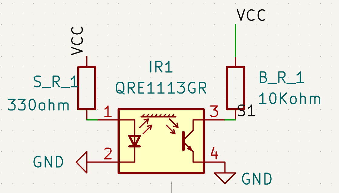
2.1 The Infrared LED Circuit
The infrared LED inside the QRE113 needs a controlled current.
The resistor connected in series with the LED determines its operating current. This is an important design decision because it affects:
Infrared illumination
Power consumption
Heat generation
Sensor response
The resistor value should be selected based on the LED's electrical characteristics and the intended supply voltage.
The goal is not simply to use the maximum possible current. The goal is to provide enough illumination for reliable surface detection while keeping power consumption reasonable.
Circuit focus
Supply → Current-limiting resistor → QRE113 IR LED → Ground
This simple part of the circuit controls how much infrared light reaches the surface.
2.2 The Phototransistor Circuit
The second half of the QRE113 is the phototransistor.
The amount of reflected infrared light changes the phototransistor's behavior. A resistor in the circuit converts this changing response into a voltage signal that the electronics can measure.
This is the part of the circuit that turns surface reflectivity into electrical information.
The key question during the design was:
How can the electrical signal from each of the 24 sensors be collected efficiently?
That leads to the next part of the design.
3. Integrating 24 Sensors
A single sensor circuit is simple. A 24-sensor array requires more careful organization.
The sensor board contains 24 repeated sensing circuits. The signals are routed through the board and made available through the board connector.
The design needed to consider:
Signal routing
Sensor spacing
Connector pin count
Power distribution
PCB size
4. From Schematic to PCB
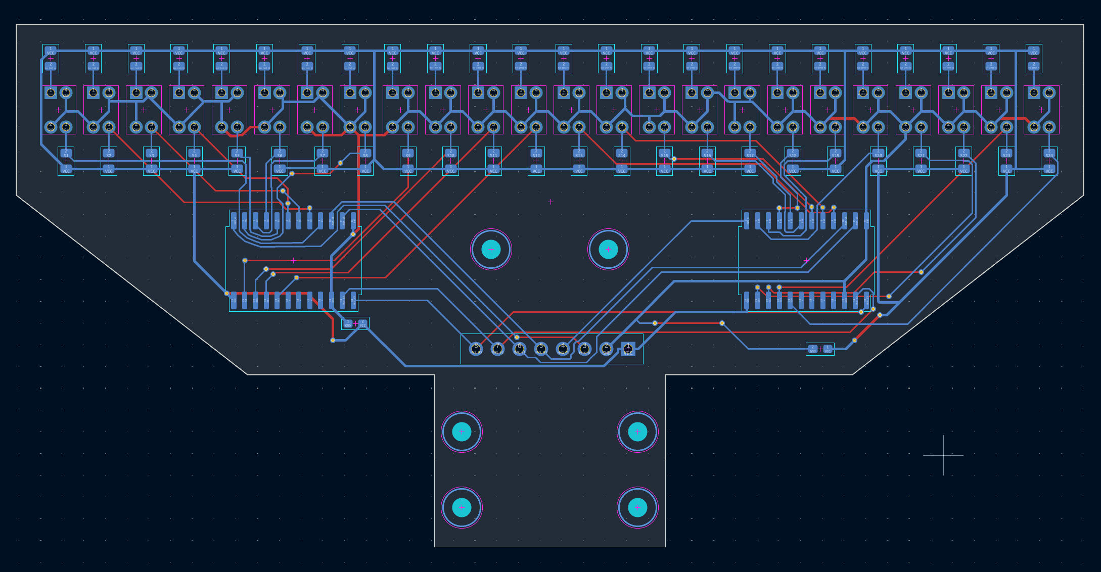
After completing the electrical design, I transferred the schematic into KiCad's PCB design workflow.
The PCB layout had two main requirements:
The sensors needed to be arranged accurately across the front edge.
The electronics and signal routing needed to fit inside the robot's mechanical design.
The sensor array is shaped specifically for the robot rather than using a standard rectangular PCB.
PCB design considerations
Sensor alignment
Trace routing
Connector placement
Component accessibility
Mechanical mounting holes
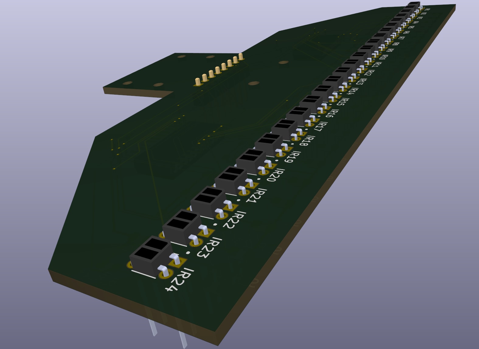
5. Sensor Board 3D View
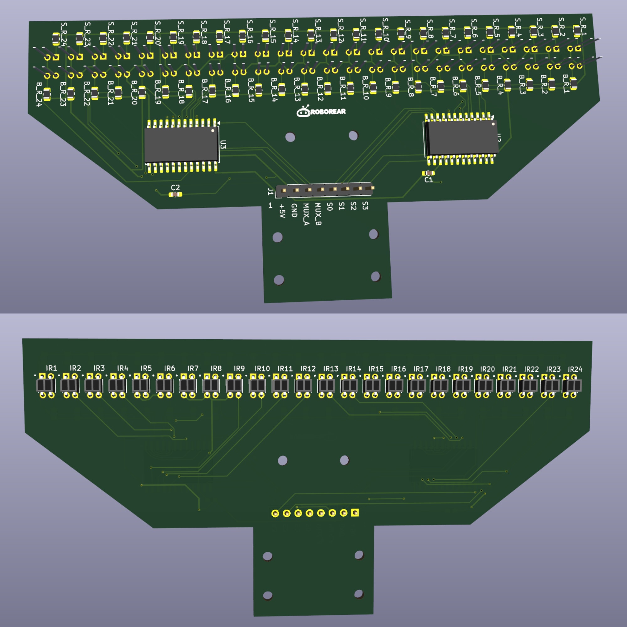
The 3D model was useful for checking the physical design before manufacturing.
It allowed me to inspect:
Sensor placement
Component clearance
Board shape
Connector orientation
Overall mechanical appearance
The physical sensor board is currently being manufactured, so these images represent the digital design and KiCad 3D model, not the final assembled hardware.
6. The Line Follower Robot Mainboard
The second major part of the project is the custom mainboard.
While the sensor board focuses on collecting information from the track, the mainboard provides the electronics needed to control the robot.
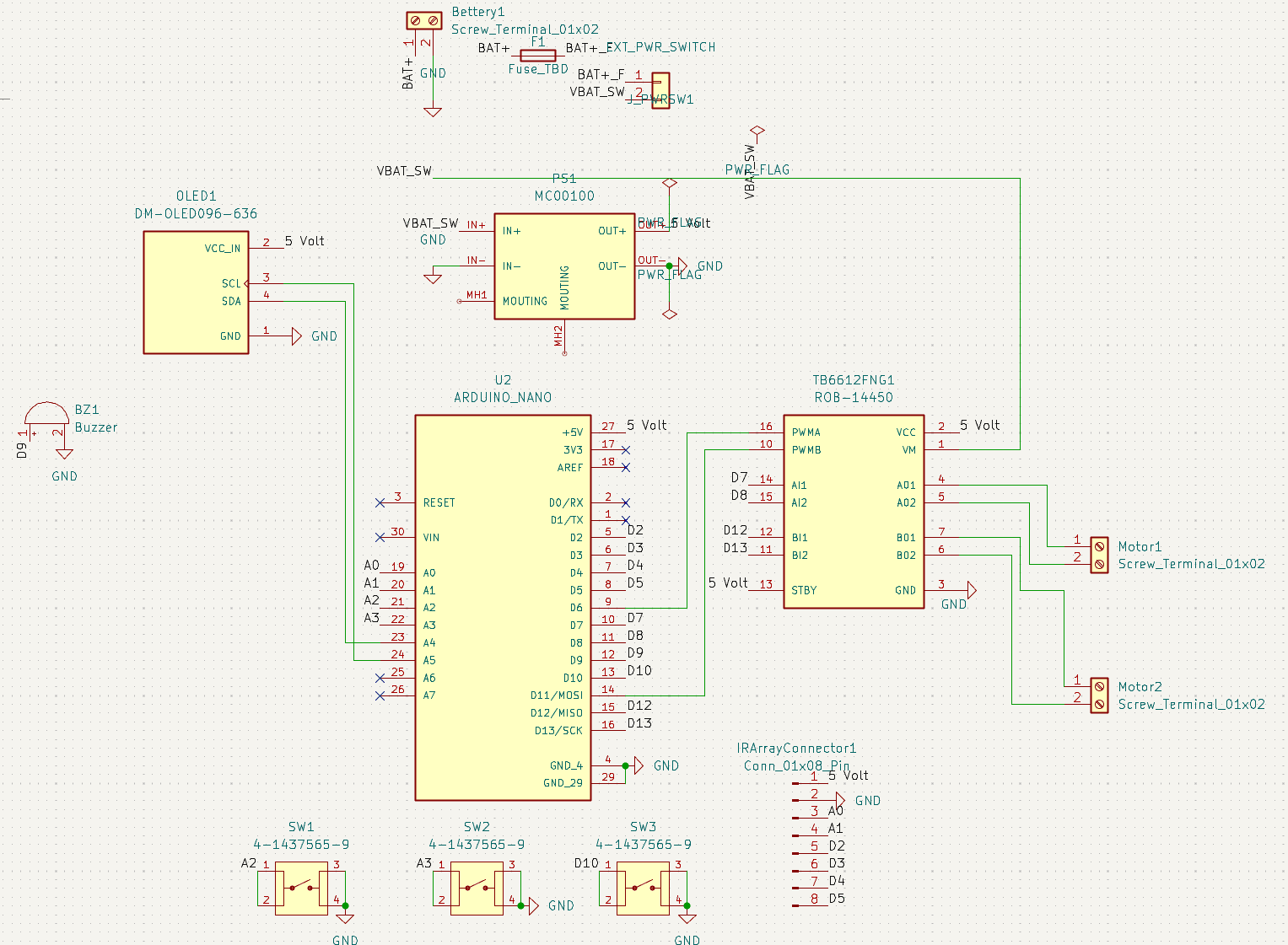
The board integrates:
Arduino Nano
Motor driver
Power regulation
OLED display
Push buttons
Buzzer
Motor connectors
Sensor board connection
6.1 Arduino Nano
The Arduino Nano acts as the main controller for the robot.
The mainboard provides connections between the controller and the sensor board, motor driver, display, buttons, and other peripherals.
6.2 Motor Driver
The motor driver is responsible for controlling the robot's motors.
The mainboard includes the motor driver as part of the PCB rather than relying on multiple separate modules. This reduces wiring and keeps the robot electronics more organized.
6.3 Power System
The power system provides the required voltage for the electronics.
The schematic includes the power input, protection and regulation circuitry required by the board.
This section should focus on your actual circuit and component choices rather than giving a generic explanation of power electronics.
7. Mainboard PCB and 3D Design
After completing the schematic, I designed the mainboard PCB in KiCad.
The component placement was planned around practical use:
Connectors are placed near the board edges.
User controls are accessible.
The display has a dedicated location.
Motor connections are grouped together.
The sensor interface is positioned for the sensor board connection.
8. Tools Used
The primary PCB design software for this project was KiCad.
I used it for:
Schematic capture
Component assignment
PCB layout
3D visualization
Design checking
I also explored AI-assisted workflows, including KiCad MCP, during the design process.
Current Project Status
At the time of writing, the sensor board and mainboard designs have been completed and sent for manufacturing.
The physical PCBs have not arrived yet, so this article focuses on the engineering and design process, particularly the electrical schematics and PCB development.
Once the boards arrive, the next steps will be:
PCB inspection
Assembly
Electrical testing
Sensor calibration
Mainboard testing
Full robot integration
A future update can cover the actual testing results and any design changes required after assembly.
Final Thoughts
The most important part of this project was designing the electronics before manufacturing the boards.
The QRE113 sensor circuit forms the foundation of the line follower system. Designing and understanding that circuit first made it possible to expand the concept into a 24-sensor array and integrate it with a custom robot mainboard.
This project is still in progress, but the schematics and PCB designs represent the foundation of the final line follower robot.
Related Guides and Resources
You can add this section near the end of your line follower blog, before the FAQ or conclusion:
Continue Learning with Roborear
If you're interested in building your own robot and designing custom electronics, these guides and resources may help:
New to PCB design? Start with the Learn PCB Design for Robotics with KiCad course. It covers the workflow from creating a schematic to PCB layout, 3D visualization, routing, design rules, and DRC. Roborear
Before designing a custom PCB, understanding basic prototyping can also help. Check out the Breadboard Connections tutorial for a practical introduction to building and checking electronic circuits. Roborear
If you're building other mobile robots, see the Arduino obstacle avoiding car guide. It is another hands-on robotics project involving sensors, motors, and robot control. Roborear
You can also explore the Roborear Projects collection for more robotics and electronics builds. Roborear
For more tutorials, experiments, and engineering projects, visit the Roborear homepage or browse the complete Roborear Blog.
Comments (0)
No comments yet. Start the discussion.