

The "Wait, Did I Just Say That?" Moment
I still remember the first time I said:
"Hey Google, turn on the desk LED."
And the light actually turned on.
I sat there for a second, staring at the bulb, half expecting it to be a coincidence. It wasn't. My ESP32 had heard me. Google Assistant had processed my voice. And together, they made a 220V light bulb obey.
That feeling? It never gets old.
At Roborear, we talk a lot about robotics—soccer bots, ESP32-CAM security systems, soldering tutorials. But there's something special about home automation. You build it once, and suddenly your room feels like the future.
This Smart Home Automation project is my step-by-step guide to building your own voice-controlled smart light using an ESP32, a relay module, and Google Assistant. No expensive smart bulbs. No cloud subscriptions. Just pure DIY satisfaction.
This video is hosted by YouTube. It loads only when you press play, and YouTube may then set cookies. Watch on YouTube
What You'll Build
| Component | What It Does |
|---|---|
| ESP32 | Connects to Wi-Fi, listens for commands |
| Relay Module | Safely switches the AC light on/off |
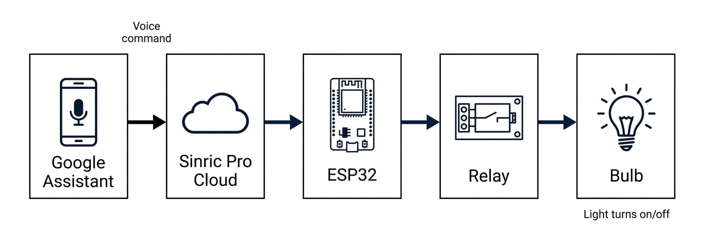
| Sinric Pro | Bridges ESP32 and Google Assistant |
| Google Assistant | Your voice command center |
The flow:
Before We Start: A Note on Safety ⚠️
This project involves 220V AC power. That's the same as your wall outlets. It can hurt you. It can start a fire. Respect it.
| ✅ DO | ❌ DON'T |
|---|---|
| Unplug everything while wiring | Work on live circuits |
| Insulate all exposed wires | Leave bare copper showing |
| Double-check connections before powering on | Rush through the AC wiring |
| Use a plastic enclosure for the relay | Touch the relay terminals while powered |
I'm a BUET mechanical engineering student—not an electrician. But I've learned to respect high voltage. If you're unsure, ask someone with experience. Safety first, then cool projects.
What You'll Need (Parts List)
Electronics (Low Voltage Side)
| Component | Specs / Notes | Approx Price (BDT) |
|---|---|---|
| ESP32 Development Board | Any version works (I used Type-C) | 600-800 |
| Relay Module | 1-channel, 5V (can use 2/4/8 channel) | 50-100 |
| Female-to-Female Jumper Wires | At least 3 | 30-50 |
| USB Cable | Data-capable, for programming | 100-200 |
Electrical (High Voltage Side)
| Component | Notes |
|---|---|
| LED Bulb + Holder | Standard household bulb |
| AC Power Plug | 2-pin or 3-pin, with wire |
| Electrical Wire | For connecting plug to bulb |
| Wire Strippers / Screwdriver | For relay terminals |
| Soldering Iron | Optional, for secure connections |

Quick Buy Links (Affiliate)
| Component | Where to Find |
|---|---|
| ESP32 Development Board | AliExpress |
| 1-Channel Relay Module | AliExpress |
| Jumper Wires (F-F) | AliExpress |
| LED Bulb Holder | AliExpress |
Step 1: Understanding the Hardware – ESP32 to Relay
The relay is the bridge between low-voltage logic and high-voltage power.
Why a Relay?
ESP32 works at 3.3V, 40mA max per pin
AC light needs 220V, hundreds of milliamps
Relay isolates them. Safe and reliable.
Connections (Low Voltage Side)
| ESP32 Pin | Relay Module Pin | Wire Color (Optional) |
|---|---|---|
| VIN (5V input) | VCC | Red |
| GND | GND | Black |
| GPIO 26 (D26) | IN1 | Yellow |
*(Photo: ESP32 and relay connected with jumper wires – clear, well-lit shot)*
Why GPIO 26? Any digital pin works. I chose 26 because it's away from default SPI/UART pins. You can use 13, 14, 27, etc.
Step 2: High-Voltage Wiring (Read This Twice)
⚠️ UNPLUG EVERYTHING BEFORE WIRING. ⚠️
Relay Terminal Basics
| Terminal | Meaning |
|---|---|
| COM (Common) | Input from AC source |
| NO (Normally Open) | Output to light – circuit OPEN when relay off |
| NC (Normally Closed) | Output – circuit CLOSED when relay off (we won't use this) |
When the ESP32 sends a HIGH signal to the relay, COM and NO connect → light turns on.
Wiring Step-by-Step
1. Prepare the AC Plug and Bulb Holder
Inside the wire, you'll find two conductors. Usually:
Brown or Red = Phase (Live)
Blue or Black = Neutral

2. Connect the Neutral Wire
Take the neutral wire from the AC plug. Connect it directly to the neutral wire of the bulb holder. Solder and insulate.
3. Connect the Phase Wire to Relay
Take the phase wire from the AC plug. Connect it to the COM terminal of the relay. Screw it tight.
4. Connect Relay to Bulb
Take another wire from the NO terminal of the relay. Connect it to the phase wire of the bulb holder.
5. Final Check
AC plug → Neutral → Bulb
AC plug → Phase → Relay COM
Relay NO → Bulb Phase
When relay clicks, COM connects to NO → circuit completes → light turns on.
Step 3: Setting Up Sinric Pro (The Cloud Bridge)
Sinric Pro is a free service that connects Google Assistant to your ESP32. It handles all the authentication and command routing.
Account Setup
1. Go to sinric.pro and create an account (free tier is plenty).
2. On the dashboard, click "Add Device".
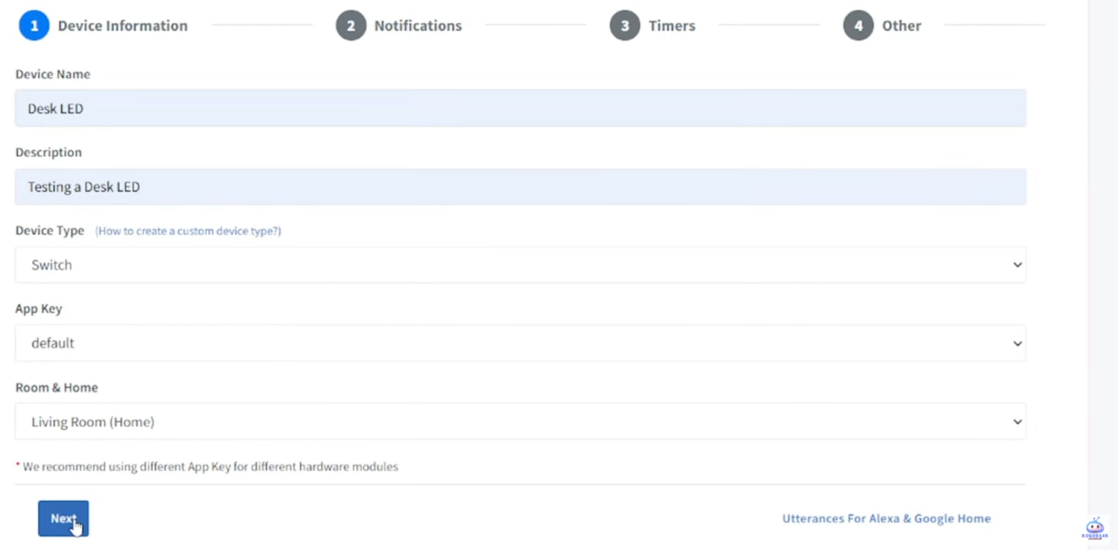
3. Fill in:
Device Name:
Desk LED(or whatever you want to call it)Device Type:
Switch
4. Save the device. You'll get a Device ID.
5. Go to Credentials section. Copy your:
App Key
App Secret
Keep these three items safe. You'll paste them into the code.
Step 3: Setting Up Sinric Pro (The Cloud Bridge)
Sinric Pro is a free service that connects Google Assistant to your ESP32. It handles all the authentication and command routing.
Account Setup
1. Go to sinric.pro and create an account (free tier is plenty).
2. On the dashboard, click "Add Device".
3. Fill in:
Device Name:
Desk LED(or whatever you want to call it)Device Type:
Switch
4. Save the device. You'll get a Device ID.
5. Go to Credentials section. Copy your:
App Key
App Secret
Keep these three items safe. You'll paste them into the code.
Step 4: The Code (Arduino IDE)
Install Required Libraries
In Arduino IDE:
Tools → Manage Libraries
Search and install:
Sinric Pro (by sinric.pro)
ArduinoJson (dependency, may install automatically)
Complete ESP32 Code
Full code available on GitHub: [Link to your GitHub repository]
// Voice-Controlled Light with ESP32 + Google Assistant
// Roborear – Shahrear Abedin Bhuiyan

#include <WiFi.h>
#include <SinricPro.h>
#include <SinricProSwitch.h>

// ---------- WiFi Credentials ----------
#define WIFI_SSID     "Your_SSID"      // Your home Wi-Fi name
#define WIFI_PASS     "Your_Password"  // Your Wi-Fi password

// ---------- Sinric Pro Credentials ----------
#define APP_KEY       "your-app-key-here"        // From Sinric Pro dashboard
#define APP_SECRET    "your-app-secret-here"     // From Sinric Pro dashboard
#define DEVICE_ID     "your-device-id-here"      // Your device ID

// ---------- Relay Pin ----------
#define RELAY_PIN     26

// ---------- LED State ----------
bool ledState = false;

// ---------- Power State Handler ----------
bool onPowerState(String deviceId, bool state) {
  Serial.printf("Device: %s turned %s\r\n", deviceId.c_str(), state ? "ON" : "OFF");
  ledState = state;
  digitalWrite(RELAY_PIN, !state);  // Note: HIGH = relay OFF (depending on your module)
  return true;
}

// ---------- WiFi Event Handler ----------
void setupWiFi() {
  WiFi.begin(WIFI_SSID, WIFI_PASS);
  Serial.print("Connecting to Wi-Fi");
  while (WiFi.status() != WL_CONNECTED) {
    delay(500);
    Serial.print(".");
  }
  Serial.println("\nWi-Fi connected");
  Serial.print("IP Address: ");
  Serial.println(WiFi.localIP());
}

// ---------- Sinric Pro Setup ----------
void setupSinricPro() {
  SinricProSwitch &mySwitch = SinricPro[DEVICE_ID];
  mySwitch.onPowerState(onPowerState);

  SinricPro.begin(APP_KEY, APP_SECRET);
  Serial.println("Sinric Pro connected");
}

// ---------- Setup ----------
void setup() {
  Serial.begin(115200);

  // Relay pin as output
  pinMode(RELAY_PIN, OUTPUT);
  digitalWrite(RELAY_PIN, HIGH);  // Start with relay OFF

  setupWiFi();
  setupSinricPro();
}

// ---------- Loop ----------
void loop() {
  SinricPro.handle();
}
⚠️ IMPORTANT: Different relay modules have different logic. Some turn ON with HIGH, others ON with LOW. Test yours:
If the relay clicks and light turns on when you upload the code, you're fine.
If the light turns on immediately or never responds, change
!statetostatein theonPowerStatefunction.
Step 5: Upload and Test
1. Connect ESP32 to your computer via USB.
2. In Arduino IDE:
Tools → Board → ESP32 Dev Module
Tools → Port → (your COM port)
3. Click Upload (right arrow).
4. Open Serial Monitor (Tools → Serial Monitor, baud 115200). You should see:
Connecting to Wi-Fi....
Wi-Fi connected
IP Address: 192.168.x.x
Sinric Pro connected
If you see "Heartbeat" messages, the ESP32 is talking to the cloud. Good.
Step 6: Link Sinric Pro to Google Home
1. Open Google Home app on your phone.
2. Tap Devices → Add → Set up device.
3. Choose "Works with Google" (or "Have something already set up?").
4. Search for "Sinric Pro" and log in with your Sinric credentials.
5. Authorize the connection. Your "Desk LED" should appear.
6. Assign it to a room (Living Room, Bedroom, etc.).

Step 7: The Moment of Truth
Everything is plugged in. ESP32 powered. Bulb in the socket. Your phone ready.
Take a breath. Then:
"Hey Google, turn on the desk LED."
Google Assistant chimes. And the light comes on.
"Hey Google, turn off the desk LED."
And it goes off.
If it works: Congratulations. You just built a voice-controlled smart light from scratch.
If it doesn't: Don't panic. Check the troubleshooting section below.
This video is hosted by YouTube. It loads only when you press play, and YouTube may then set cookies. Watch on YouTube
Troubleshooting
| Problem | Likely Cause | Fix |
|---|---|---|
| ESP32 not connecting to Wi-Fi | Wrong SSID/password, or 5GHz network | Check credentials; ESP32 needs 2.4GHz |
| Sinric Pro shows offline | Network issue, or credentials wrong | Recheck App Key/Secret in code |
| Relay clicks but light doesn't turn on | AC wiring issue | Check COM and NO connections; ensure bulb works |
| Light is always on | Relay logic inverted | In code, change !state to state in onPowerState |
| Google Assistant doesn't find device | Sinric Pro not linked | Re-link in Google Home app |
| ESP32 resets when relay triggers | Power supply issue | ESP32 needs stable 5V; try different USB cable/power bank |
Frequently Asked Questions
How long do I get support?
Even the all-powerful Pointing has no control about the blind texts it is an almost unorthographic life One day however a small line
Do I need to renew my license?
Marks and devious Semikoli but the Little Blind Text didn’t listen. She packed her seven versalia, put her initial into the belt and made herself on the way.
How This Compares to Commercial Smart Bulbs
| Feature | DIY ESP32 Project | Commercial Smart Bulb |
|---|---|---|
| Price | ~800-1000 BDT (one-time) | 1500-3000 BDT per bulb |
| Voice Control | ✅ Yes (Google Assistant) | ✅ Yes |
| Internet Required | ✅ Yes (cloud) | ✅ Yes |
| Works with Existing Bulb | ✅ Yes (any bulb) | ❌ No (replaces bulb) |
| Learning Experience | ✅ Priceless | ❌ None |
| Reliability | Good (depends on network) | Excellent |
| Aesthetics | Visible ESP32/relay | Invisible (bulb only) |
For me, the learning experience alone makes the DIY route worth it. Plus, I can control any light—not just special smart bulbs.
What's Next? Upgrades to Try
This is a foundation. Here's how to level up:
| Upgrade | What You'll Need |
|---|---|
| Control multiple lights | 2/4/8-channel relay module; modify code |
| Add manual switch | Toggle switch wired in parallel with relay |
| Voice + phone control | Use Sinric Pro dashboard on phone |
| Add sensor (light/motion) | PIR sensor, LDR – trigger lights automatically |
| Make it portable | 18650 battery + TP4056 charger |
| Add enclosure | 3D print a case for ESP32 + relay |
I'm planning to add a PIR motion sensor to my desk light. "Hey Google, turn on when I walk in" – one step closer to fully automated.
FAQs
Frequently Asked Questions
1. Why won't my ESP32 connect to WiFi? Or why is it constantly rebooting?
This is the most common issue, and it usually comes down to WiFi credentials or power. First, make absolutely sure you have entered your WiFi SSID (name) and password correctly in the code. The ESP32 is case-sensitive. Second, check that you are using a 2.4GHz WiFi network. The ESP32 cannot connect to 5GHz networks. Most modern routers broadcast both, but your phone or computer might be connected to 5GHz. You need to use the 2.4GHz band for initial setup. Third, the ESP32 draws a lot of power when connecting to WiFi. If you are powering it from your computer's USB port, try using a dedicated 5V phone charger (at least 1A). A weak power supply is a very common cause of random reboots, especially during WiFi connection.
2. The relay clicks but my light bulb doesn't turn on. What's wrong?
This means your ESP32 and code are working perfectly, but your AC wiring has an issue. The relay clicking tells you the low-voltage (3.3V) side is working. The problem is on the high-voltage (220V) side. Double-check your AC wiring: The "hot" (phase/live) wire from your wall plug must go to the relay's COM terminal. The wire going to your light bulb must be connected to the relay's NO (Normally Open) terminal. The neutral wire must be connected directly from the wall plug to the light bulb, bypassing the relay. When the relay clicks, it connects the COM and NO terminals, completing the circuit and turning the light on.
3. My ESP32 code uploads, but Google Home can't find the device. How do I fix this?
This is usually an account linking or device synchronization issue. Follow these steps in order: First, after uploading the code, open the Arduino IDE Serial Monitor (set to 115200 baud). You should see the ESP32 connect to WiFi and then a message like "Sinric Pro Connected". If you don't see this message, your device isn't reaching the Sinric Pro cloud server. Second, make sure you have correctly copied the Device ID, App Key, and App Secret from your Sinric Pro dashboard directly into your Arduino code. Even a missing character will prevent linking. Third, in the Google Home app, you need to manually sync your devices. Go to the "Devices" section, pull down from the top to refresh, or say "Hey Google, sync my devices." It can take up to 30 seconds for new devices to appear after linking.
Affiliate Disclosure
Some links in this post are affiliate links. If you purchase through them, I may earn a small commission at no extra cost to you. This helps support Roborear. Thanks!
Tags