

The "I Control This" Moment | Joystick with ESP32
Remember old-school gaming controllers? PlayStation, Xbox, arcade machines.
That joystick in your thumb? It wasn't magic.
Inside, it's just two variable resistors (potentiometers) and a button. Your thumb moves the stick. The stick moves the potentiometers. The potentiometers change voltage. The microcontroller reads that voltage.
And suddenly, you're controlling a robot. Or a camera. Or a game.
Today, you'll learn exactly how a joystick works. You'll wire it to Joystick with ESP32. You'll read real-time X and Y values. You'll detect button presses.
And by the end, you'll be ready to build your own RC car, robot arm, or game controller.
This video is hosted by YouTube. It loads only when you press play, and YouTube may then set cookies. Watch on YouTube
What is a Joystick Module?
A joystick module is an input device that tells you two things:
| Axis | What It Measures |
|---|---|
| X-axis | Left (-) to Right (+) movement |
| Y-axis | Forward (-) to Backward (+) movement |
Plus, most modules have a push button when you press the stick down.
Inside the module:
Two 10kΩ potentiometers (one for X, one for Y)
One momentary push button (the "SW" pin)
Springs that return the stick to center when released
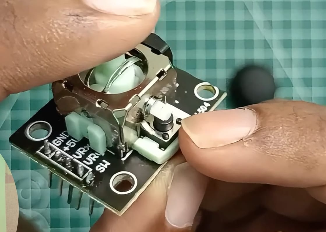
How the Joystick Outputs Values | Joystick with ESP32
When you move the joystick, the potentiometers change resistance. This changes the voltage on the signal pins.
The ESP32 reads this voltage using its ADC (Analog to Digital Converter) pins.
| Input | Voltage Range | ESP32 Reading Range |
|---|---|---|
| Minimum (full left/up) | 0V | 0 |
| Center (rest position) | ~1.65V | ~2048 |
| Maximum (full right/down) | 3.3V | 4095 |
Important: The ESP32's ADC is 12-bit, giving readings from 0 to 4095. This is more precise than Arduino Uno's 10-bit (0-1023) range.
What You'll Need to Connect the Joystick with ESP32
| Component | Specs / Notes | Price (USD) |
|---|---|---|
| ESP32 Development Board | Any 30-pin version | $5.00 - $7.00 |
| Joystick Module | XY axes + center push button | $1.00 - $2.00 |
| Breadboard | 400 points (optional) | $1.00 - $2.00 |
| Jumper Wires | Male-to-Female and Male-to-Male | $2.00 - $4.00 |
| USB Cable | For programming and power | $2.00 - $4.00 |
Total: ~$11.00 - $19.00 USD
Quick Buy Links
| Component | Where to Find |
|---|---|
| ESP32 Development Board | AliExpress |
| Joystick Module | AliExpress |
| Breadboard (400 points) | AliExpress |
| Jumper Wires Kit | AliExpress |
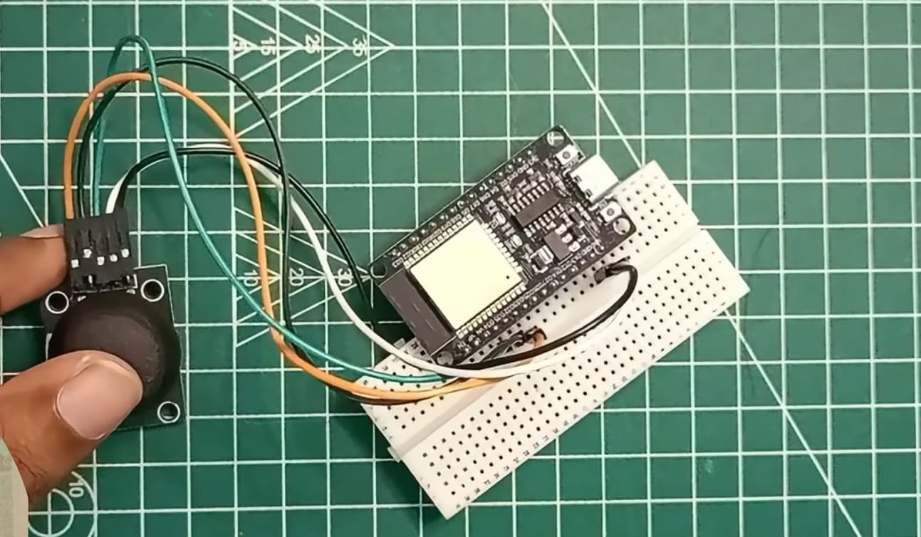
Wiring the Joystick to ESP32 | Joystick with ESP32
The joystick module has 5 pins:
| Joystick Pin | ESP32 Pin | Function |
|---|---|---|
| GND | GND | Ground |
| 5V (or VCC) | VIN (5V) | Power (5V works, 3.3V also works but range may differ) |
| VRx (X-axis) | GPIO 34 | Analog input (ADC) |
| VRy (Y-axis) | GPIO 35 | Analog input (ADC) |
| SW (button) | GPIO 15 | Digital input (with internal pull-up) |
Note about analog pins: GPIO 34, 35, 36, and 39 are input-only pins. They don't have internal pull-up or pull-down resistors, but they're perfect for reading analog sensors like this joystick.
The Code | Joystick with ESP32
This code reads the joystick position 50 times per second and prints the values to the Serial Monitor.
// ============================================================
// ESP32 Joystick Reader - Complete Beginner Guide
// Reads X/Y analog values and button state
// ============================================================

// Pin Definitions
#define JOYSTICK_X 34
#define JOYSTICK_Y 35
#define JOYSTICK_SW 15

// Variables for calibration
int xValue = 0;
int yValue = 0;
int swValue = 0;

void setup() {
  Serial.begin(115200);

  // Configure button pin with internal pull-up
  // (INPUT_PULLUP means pin reads HIGH when not pressed, LOW when pressed)
  pinMode(JOYSTICK_SW, INPUT_PULLUP);

  // Analog pins don't need pinMode setup

  Serial.println("ESP32 Joystick Reader");
  Serial.println("=====================");
  Serial.println("Move the joystick and press the button...\n");
  delay(1000);
}

void loop() {
  // Read analog values (0-4095)
  xValue = analogRead(JOYSTICK_X);
  yValue = analogRead(JOYSTICK_Y);

  // Read digital button (LOW when pressed, HIGH when not pressed)
  // The ! (NOT) inverts the reading so pressed = true
  bool buttonPressed = !digitalRead(JOYSTICK_SW);

  // Map values to -100 to +100 range for easier understanding
  int mappedX = map(xValue, 0, 4095, -100, 100);
  int mappedY = map(yValue, 0, 4095, -100, 100);

  // Small dead zone to eliminate jitter at center
  if (abs(mappedX) < 10) mappedX = 0;
  if (abs(mappedY) < 10) mappedY = 0;

  // Print to Serial Monitor
  Serial.print("X: ");
  Serial.print(xValue);
  Serial.print(" (");
  Serial.print(mappedX);
  Serial.print(") | Y: ");
  Serial.print(yValue);
  Serial.print(" (");
  Serial.print(mappedY);
  Serial.print(") | Button: ");
  Serial.println(buttonPressed ? "PRESSED" : "released");

  delay(50);  // Read 20 times per second (smooth enough, not too fast)
}
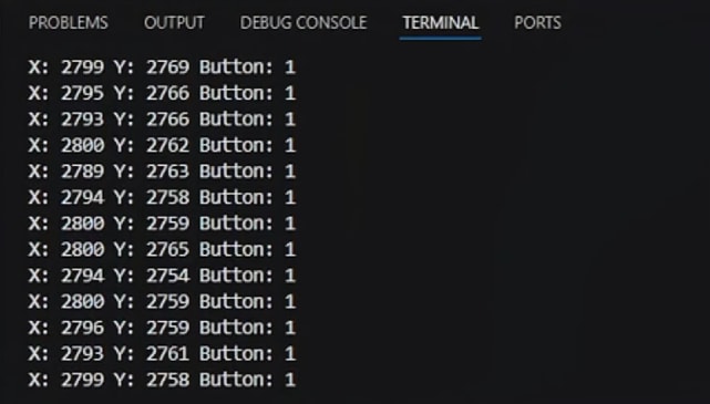
Understanding the Serial Monitor Output | Joystick with ESP32
After uploading, open Serial Monitor (Tools → Serial Monitor, baud 115200).
Move the joystick. You'll see something like:
text
X: 2048 (0) | Y: 2048 (0) | Button: released
X: 4095 (100) | Y: 2048 (0) | Button: released
X: 0 (-100) | Y: 2048 (0) | Button: released
X: 2048 (0) | Y: 4095 (100) | Button: released
X: 2048 (0) | Y: 0 (-100) | Button: released
X: 2048 (0) | Y: 2048 (0) | Button: PRESSED| Reading | Meaning |
|---|---|
| X: 2048 (0) | Joystick centered left-right |
| X: 4095 (100) | Full right |
| X: 0 (-100) | Full left |
| Y: 2048 (0) | Joystick centered forward-back |
| Y: 4095 (100) | Full forward (away from you) |
| Y: 0 (-100) | Full backward (toward you) |
| Button: PRESSED | Joystick knob pressed down |
Full ESP32 RC car tutorial - Build Your Own ESP32 RC Car: Wireless Joystick Controller Guide for Beginners
Calibrating Your Joystick | Joystick with ESP32
Every joystick is slightly different. The center position might not be exactly 2048.
To calibrate:
Run the code and open Serial Monitor
Let go of the joystick (let it center itself)
Note the X and Y values at rest
Adjust the map function if needed:
cpp
// If your center X is 2100 instead of 2048, adjust the mapping:
int mappedX = map(xValue, 0, 4095, -100, 100);
// Or apply an offset:
int mappedX = map(xValue - 52, 0, 4095, -100, 100);
Most of the time, the default mapping is fine. The dead zone (if (abs(mappedX) < 10) mappedX = 0;) will ignore small center offsets.
What You Can Control with a Joystick | Joystick with ESP32
Once you can read joystick values, you can control almost anything:
| Output | How to Control |
|---|---|
| LED brightness | Map Y value (0-4095) to PWM value (0-255) |
| Servo angle | Map X value to servo degrees (0-180) |
| Motor speed | Map Y value to motor speed (-255 to +255) |
| RGB LED color | Use X for red, Y for green |
| Camera pan/tilt | X controls pan servo, Y controls tilt servo |
| Robot movement | X = turning, Y = forward/backward |

Controlling servos with ESP32 - How to Control Servo Motors with ESP32 using VS Code & PlatformIO | Robotics for Beginners
Simple Project: Joystick-Controlled LED Brightness | Joystick with ESP32
Here's a quick project to test your joystick. It uses the Y-axis to control an LED's brightness.
Add to your circuit: LED anode (+) → GPIO 26 through 220Ω resistor, LED cathode (-) → GND.
#define JOYSTICK_Y 35
#define LED_PIN 26

int yValue = 0;
int ledBrightness = 0;

void setup() {
  Serial.begin(115200);
  pinMode(LED_PIN, OUTPUT);
  ledcSetup(0, 5000, 8);
  ledcAttachPin(LED_PIN, 0);
}

void loop() {
  yValue = analogRead(JOYSTICK_Y);
  ledBrightness = map(yValue, 0, 4095, 0, 255);
  ledcWrite(0, ledBrightness);

  Serial.print("Y: ");
  Serial.print(yValue);
  Serial.print(" | Brightness: ");
  Serial.println(ledBrightness);

  delay(50);
}
Push the joystick forward → LED gets brighter. Pull back → LED dims.
More ESP32 output projects - Sound Sensor Module Project: ESP32 Sound Activated LED + Buzzer Project
Mini Project: Joystick-Controlled Servo (Pan Camera)
Let's build a simple but fun project: control a servo motor using the joystick's X-axis. This is the perfect next step after learning to read joystick values.
What You'll Need | Joystick with ESP32
| Component | Quantity |
|---|---|
| ESP32 (from the main project) | 1 |
| Joystick module (already wired) | 1 |
| SG90 Servo motor | 1 |
| Jumper wires (female-to-female) | 3 |
Additional Wiring | Joystick with ESP32
| Servo Wire | ESP32 Pin |
|---|---|
| Brown/Black (GND) | GND |
| Red (VCC) | 5V (or external 5V power) |
| Orange/Yellow (Signal) | GPIO 13 |
Power note: A single SG90 servo can be powered from the ESP32's 5V pin for testing. For multiple servos or長時間 use, use external power.
The Code
#include <ESP32Servo.h>

// Joystick pins (same as main project)
#define JOYSTICK_X 34
#define JOYSTICK_Y 35
#define JOYSTICK_SW 15

// Servo pin
#define SERVO_PIN 13

Servo myServo;

void setup() {
  Serial.begin(115200);

  // Attach servo
  myServo.attach(SERVO_PIN);

  // Configure joystick button
  pinMode(JOYSTICK_SW, INPUT_PULLUP);

  Serial.println("Joystick Servo Control Ready!");
  Serial.println("Move joystick left/right to control servo angle");
}

void loop() {
  // Read joystick X-axis value (0-4095)
  int xValue = analogRead(JOYSTICK_X);

  // Map to servo angle (0-180 degrees)
  int angle = map(xValue, 0, 4095, 0, 180);

  // Move servo
  myServo.write(angle);

  // Print to Serial Monitor
  Serial.print("X: ");
  Serial.print(xValue);
  Serial.print(" | Angle: ");
  Serial.println(angle);

  // Optional: Read joystick button
  bool buttonPressed = !digitalRead(JOYSTICK_SW);
  if (buttonPressed) {
    Serial.println("Button pressed!");
    myServo.write(90);  // Center servo when button pressed
    delay(500);
  }

  delay(15);  // Small delay for smooth servo movement
}
How It Works | Joystick with ESP32
| Joystick Position | Servo Angle |
|---|---|
| Full left (X = 0) | 0 degrees |
| Center (X = 2048) | 90 degrees |
| Full right (X = 4095) | 180 degrees |
| Button press | Centers servo to 90 degrees |
What You'll See | Joystick with ESP32
Move the joystick left and right. The servo arm will follow your movement smoothly. Press the joystick down – the servo centers automatically.
Challenge Yourself | Joystick with ESP32
Once this works, try these upgrades:
| Challenge | What to Change |
|---|---|
| Use Y-axis | Change analogRead(JOYSTICK_Y) and map to servo |
| Add second servo | Connect second servo to GPIO 14, one for X, one for Y |
| Reverse direction | Swap map values: map(xValue, 0, 4095, 180, 0) |
| Finer control | Reduce movement range: map(xValue, 0, 4095, 45, 135) |
Complete System Diagram | Joystick with ESP32
text
Joystick X-axis → ESP32 GPIO 34 → map(0-4095 → 0-180) → Servo on GPIO 13This mini project teaches you:
✅ How to read analog input from a joystick
✅ How to convert sensor values to control outputs
✅ How to control a servo with PWM
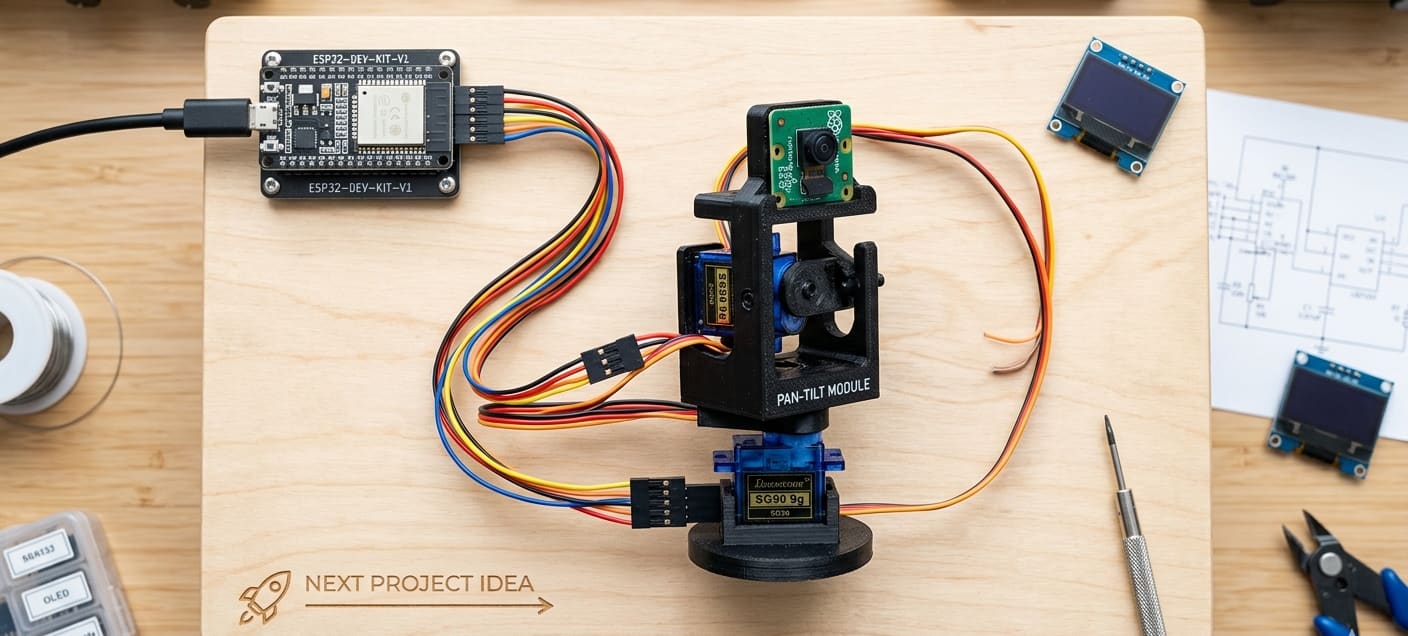
✅ Real-world application: camera pan mechanism
This is the exact same principle used in CCTV pan-tilt systems, robot head movement, and RC camera gimbals. Once you master this, you can build a complete pan-tilt camera system by adding a second servo for tilt control!
Troubleshooting | Joystick with ESP32
| Problem | Likely Cause | Fix |
|---|---|---|
| Serial Monitor shows no values | Wrong baud rate | Set Serial Monitor to 115200 baud |
| Values stuck at 4095 or 0 | VCC or GND not connected | Check joystick power wiring |
| X and Y values swapped | Wiring mismatch | Swap VRx and VRy pins, or swap in code |
| Button always shows "released" | SW pin not connected | Check jumper from SW to GPIO 15 |
| Button always shows "pressed" | Missing pull-up | Use pinMode(JOYSTICK_SW, INPUT_PULLUP) |
| Values jump erratically | Floating analog pins | Analog pins are fine, but check power stability |
| Center position not at 2048 | Normal variation | Add dead zone or calibration offset |
🎥 Watch the Complete Video Tutorial | Joystick with ESP32
See the joystick in action with real-time demonstrations and code explanation:
📺 How to Use a Joystick with ESP32 | Complete Guide for Beginners
👉 Don't forget to Subscribe to Roborear on YouTube for more ESP32 tutorials and robotics projects every week!
How It Works | Joystick with ESP32
| Joystick Position | Servo Angle |
|---|---|
| Full left (X = 0) | 0 degrees |
| Center (X = 2048) | 90 degrees |
| Full right (X = 4095) | 180 degrees |
| Button press | Centers servo to 90 degrees |
What You'll See | Joystick with ESP32
Move the joystick left and right. The servo arm will follow your movement smoothly. Press the joystick down – the servo centers automatically.
Challenge Yourself | Joystick with ESP32
Once this works, try these upgrades:
| Challenge | What to Change |
|---|---|
| Use Y-axis | Change analogRead(JOYSTICK_Y) and map to servo |
| Add second servo | Connect second servo to GPIO 14, one for X, one for Y |
| Reverse direction | Swap map values: map(xValue, 0, 4095, 180, 0) |
| Finer control | Reduce movement range: map(xValue, 0, 4095, 45, 135) |
Complete System Diagram | Joystick with ESP32
text
Joystick X-axis → ESP32 GPIO 34 → map(0-4095 → 0-180) → Servo on GPIO 13This mini project teaches you:
✅ How to read analog input from a joystick
✅ How to convert sensor values to control outputs
✅ How to control a servo with PWM
✅ Real-world application: camera pan mechanism
This is the exact same principle used in CCTV pan-tilt systems, robot head movement, and RC camera gimbals. Once you master this, you can build a complete pan-tilt camera system by adding a second servo for tilt control!
Your Turn | Joystick with ESP32
The joystick is one of the most versatile input devices for robotics. Master it, and you can control anything.
Now go build something. An RC car. A robot arm. A game controller.
The joystick is waiting. I hope you liked the tutorial on the Joystick with ESP32 connection. Read all Roborear tutorials for beginners - Blogs
FAQs
Frequently Asked Questions
1. Why are my joystick values stuck at 4095 or 0? - Joystick with ESP32
This means your ESP32 isn't reading varying voltage from the joystick. First, check that you connected the joystick's VCC pin to the ESP32's VIN (5V) pin, not 3.3V. While 3.3V works, the voltage range will be different. The more common issue is a missing GND connection – the joystick needs a ground reference to output varying voltages. Second, verify you're using analog pins (GPIO 34, 35, 36, or 39). These are the only pins on the ESP32 that support analog input. Third, if values are stuck at 0, your VRx/VRy wires might be swapped with GND or VCC. Double-check the wiring against the pin table. Finally, test with a multimeter. Measure voltage between GND and VRx while moving the joystick. You should see voltage change from 0V to ~3.3V. If not, the joystick module may be faulty.
2. My readings are jumpy or unstable, even when the joystick is still - Joystick with ESP32
This is usually electrical noise, not a faulty joystick. First, add a small dead zone in your code. The example code already includes if (abs(mappedX) < 10) mappedX = 0; – this ignores tiny movements near center. Adjust the 10 value higher (e.g., 15 or 20) if needed. Second, check your power supply. The ESP32's analog readings can be noisy when powered from a computer's USB port. Try a phone charger or add a 100µF capacitor between 3.3V and GND near the joystick. Third, the ESP32's ADC is known to have non-linearity, especially at extreme values. For most joystick applications (RC car, robot arm), this isn't noticeable. For precision applications, consider averaging multiple readings: cpp int smoothRead(int pin) { int total = 0; for (int i = 0; i < 10; i++) { total += analogRead(pin); delay(1); } return total / 10; } Fourth, keep wires short. Long jumper wires act as antennas and pick up noise.
3. How do I use this joystick to control a servo or motor? - Joystick with ESP32
The core concept is mapping the joystick's analog values to control signals. For a servo (from earlier tutorial library): cpp #include
Servo myServo; int servoAngle = map(xValue, 0, 4095, 0, 180); myServo.write(servoAngle); For a motor (using L298N or similar driver): cpp int motorSpeed = map(yValue, 0, 4095, -255, 255); if (motorSpeed > 0) { digitalWrite(IN1, HIGH); digitalWrite(IN2, LOW); } else { digitalWrite(IN1, LOW); digitalWrite(IN2, HIGH); } ledcWrite(0, abs(motorSpeed)); For an RGB LED: cpp int red = map(xValue, 0, 4095, 0, 255); int green = map(yValue, 0, 4095, 0, 255); ledcWrite(0, red); // Assuming red on channel 0 ledcWrite(1, green); // Assuming green on channel 1 The key pattern is: Read analog → Map to output range → Send to output device. For a complete RC car project using two ESP32s (one for joystick, one for car), check the internal link to the ESP32 RC Car tutorial below.
4. Can I use two joysticks with one ESP32? How many analog pins do I need? - Joystick with ESP32
Yes, absolutely! Using two joysticks is common for projects like dual-stick game controllers, RC tank controls, or camera + movement control . Each joystick requires: 2 analog pins (VRx and VRy) 1 digital pin (SW button) For two joysticks, you need 4 analog pins and 2 digital pins. Important: GPIO 34, 35, 36, and 39 are input-only pins – perfect for analog joysticks since they don't need output functionality. For a complete dual-joystick controller example, you can adapt the single joystick code by creating separate variables and reading each joystick independently in the loop. Many RC projects use this setup for controlling movement with one joystick and camera/servo with the other.
5. Why are my joystick values jumping around even when the stick is centered? - Joystick with ESP32
This is called ADC noise or signal jitter, and it's completely normal, especially with ESP32's built-in analog-to-digital converter. The ESP32 has a 12-bit ADC, which gives readings from 0 to 4095. When the joystick is centered, the theoretical value should be around 2048. But in reality, you'll see values like 2042, 2051, 2038 – constantly fluctuating by 5-15 counts. The fix: Add a "dead zone" in your code. This dead zone prevents your robot or servo from twitching when the joystick is centered . Any movement less than 10% of full range is treated as "center." If the jitter is extreme (50+ count jumps), check your power supply – noisy power can cause unstable ADC readings . Adding a 100µF capacitor across the joystick's VCC and GND can help stabilize the readings.
Tags