

The "My Desk Came Alive" Moment
I was sitting at my desk, bored.
Music playing. Lights on. Nothing special.
Then I built this.
A sound sensor on an ESP32. Three LEDs. A buzzer.
I clapped my hands. 🔵 Blue LED glowed softly.
I spoke louder. 🟢 Green LED lit up.
I shouted (sorry, roommates). 🔴 Red LED flashed. The buzzer screamed.
My desk was reacting to sound. Sound sensor module project sounds amazing, right?
And the best part? It took me 20 minutes to build.
This is the perfect beginner project. Simple wiring. Easy code. And incredibly satisfying when your voice actually controls something.
This video is hosted by YouTube. It loads only when you press play, and YouTube may then set cookies. Watch on YouTube
What You'll Build
A sound-activated light and alarm system that:
| Sound Level | LED Color | Buzzer |
|---|---|---|
| 🤫 Quiet / Silence | OFF | OFF |
| 🗣️ Normal talking | 🔵 Blue LED ON | OFF |
| 📢 Loud voice | 🟢 Green LED ON | OFF |
| 🔔 Clapping / Shouting | 🔴 Red LED ON | ✅ ON for 1 second |
The sensor measures sound intensity in real-time. Louder sound = more LEDs light up!
*(Diagram: Sound sensor → ESP32 reads value → LEDs + Buzzer react)*
What You'll Need
Hardware Components
| Component | Specs / Notes | Price (USD) |
|---|---|---|
| ESP32 Development Board | Any 30-pin version | $5.00 - $7.00 |
| Sound Sensor Module | LM393, 3.3V-5V, analog output | $2.00 - $4.00 |
| Red LED | 5mm, any brightness | $0.05 - $0.10 |
| Green LED | 5mm, any brightness | $0.05 - $0.10 |
| Blue LED | 5mm, any brightness | $0.05 - $0.10 |
| 220Ω Resistors (3x) | For LEDs (current limiting) | $0.05 - $0.10 each |
| Passive Buzzer | 5V | $0.50 - $1.00 |
| Breadboard | 400 points | $1.00 - $2.00 |
| Jumper Wires | Male-to-female & male-to-male | $1.00 - $2.00 |
| USB Cable | For power and programming | $2.00 - $4.00 |
Total: ~$12.00 - $21.00 USD
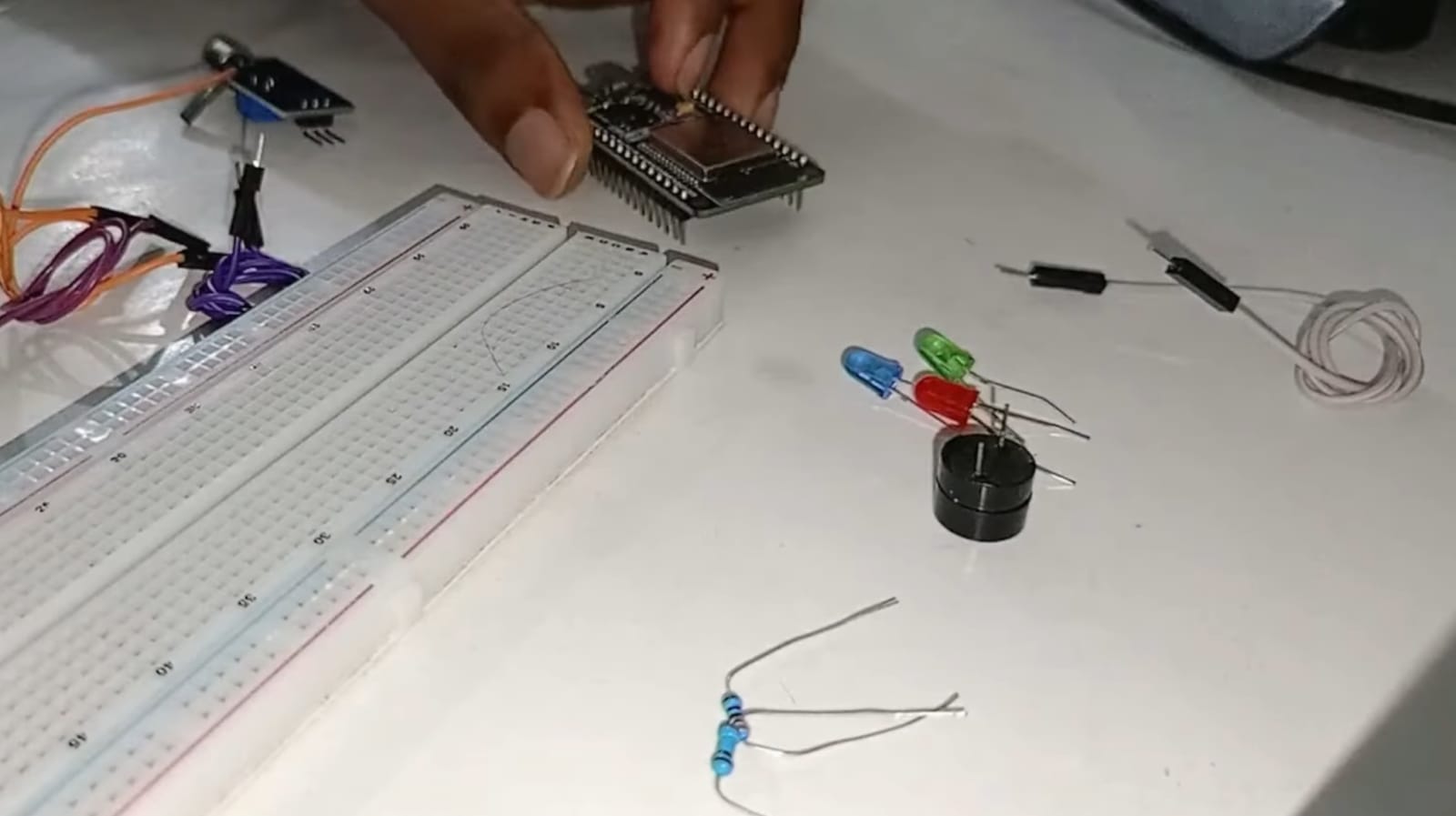
Quick Buy Links
| Component | Where to Find |
|---|---|
| ESP32 Development Board | AliExpress |
| Sound Sensor Module (LM393) | AliExpress |
| LED Assorted Kit | AliExpress |
| 220Ω Resistors (Pack) | AliExpress |
| Passive Buzzer | AliExpress |
| Breadboard + Jumper Kit | AliExpress |
How the Sound Sensor Works
The LM393 sound sensor module has two outputs:
| Output | What It Does | We'll Use? |
|---|---|---|
| Analog (AO) | Outputs voltage proportional to loudness (0-3.3V) | ✅ YES – for this project |
| Digital (DO) | Goes LOW when sound exceeds threshold | ❌ NO – not needed |
On the module, you'll find:
| Component | Function |
|---|---|
| Potentiometer | Adjusts sensitivity (turn with a small screwdriver) |
| Power LED | Lights up when module has power |
| Comparator LED | Lights up when digital output triggers |
How it works:
Microphone picks up sound
Circuit converts sound waves to voltage
Louder sound = higher voltage on AO pin
ESP32 reads this voltage (0-4095 ADC value)
We set thresholds in code to trigger different LEDs

Read sensor values in my distance alarm project - This $5 Sensor Knows When You’re Too Close (ESP32 Distance Alarm System)
Wiring It Up
Sound Sensor
| Sound Sensor Pin | ESP32 Pin | Notes |
|---|---|---|
| VCC | 3.3V | Use 3.3V, not 5V! |
| GND | GND | Common ground |
| AO (Analog Out) | GPIO 34 | ADC input pin |
⚠️ Important: The sound sensor works at 3.3V. Connect to ESP32's 3.3V pin, not 5V.
LEDs (through 220Ω resistors)
| LED | ESP32 Pin | Polarity |
|---|---|---|
| Blue LED | GPIO 26 | Anode (+) to pin, Cathode (-) to GND |
| Green LED | GPIO 27 | Anode (+) to pin, Cathode (-) to GND |
| Red LED | GPIO 14 | Anode (+) to pin, Cathode (-) to GND |
Buzzer
| Buzzer Pin | ESP32 Pin |
|---|---|
| Positive (+) | GPIO 12 |
| Negative (-) | GND |
Setting up ESP32 with VS Code guide - Robotics for Beginners: Learn ESP32 PlatformIO with VS Code | Blink LED Tutorial
// Read sound sensor value (0-4095)
int soundValue = analogRead(SOUND_SENSOR_PIN);

// Map to 0-100 range for easier understanding
int soundLevel = map(soundValue, 0, 4095, 0, 100);

// Decision logic based on sound level
if (soundLevel > 70) {
  // Very loud – red LED + buzzer
  digitalWrite(RED_LED, HIGH);
  digitalWrite(GREEN_LED, LOW);
  digitalWrite(BLUE_LED, LOW);
  digitalWrite(BUZZER_PIN, HIGH);
  delay(200);
  digitalWrite(BUZZER_PIN, LOW);
}
else if (soundLevel > 40) {
  // Medium loud – green LED
  digitalWrite(RED_LED, LOW);
  digitalWrite(GREEN_LED, HIGH);
  digitalWrite(BLUE_LED, LOW);
}
else if (soundLevel > 10) {
  // Quiet – blue LED
  digitalWrite(RED_LED, LOW);
  digitalWrite(GREEN_LED, LOW);
  digitalWrite(BLUE_LED, HIGH);
}
else {
  // Silence – all LEDs off
  digitalWrite(RED_LED, LOW);
  digitalWrite(GREEN_LED, LOW);
  digitalWrite(BLUE_LED, LOW);
}
Adjusting Sensitivity
The sound sensor has a potentiometer (blue box with a cross slot) on the back.
| Turn | Effect |
|---|---|
| Clockwise | More sensitive (detects softer sounds) |
| Counter-clockwise | Less sensitive (only loud sounds trigger) |
How to tune it:
Upload the code
Open Serial Monitor (115200 baud)
Make a sound (clap, talk, snap fingers)
Watch the
Sound LevelpercentageAdjust potentiometer until: whispers show ~10-20%, claps show ~80-90%
Testing Your Project
| Action | Expected Result |
|---|---|
| Silence / no sound | All LEDs OFF |
| Whisper or soft talk | 🔵 Blue LED ON |
| Normal conversation | 🟢 Green LED ON |
| Clap or shout | 🔴 Red LED ON + Buzzer beeps |
This video is hosted by YouTube. It loads only when you press play, and YouTube may then set cookies. Watch on YouTube
Make It Your Own (Upgrades)
| Upgrade | Difficulty | What You'll Need |
|---|---|---|
| Add more LEDs | ⭐ Easy | Extra LEDs + resistors |
| RGB LED instead | ⭐ Easy | Single RGB LED (common cathode) |
| LED strip | ⭐⭐ Medium | WS2812B addressable LED strip |
| Change colors | ⭐ Easy | Modify digitalWrite() in code |
| Adjust thresholds | ⭐ Easy | Change QUIET_THRESHOLD, MEDIUM_THRESHOLD, LOUD_THRESHOLD |
| Add OLED display | ⭐⭐ Medium | 0.96" OLED – show sound level as bar graph |
| Battery power | ⭐⭐ Medium | 18650 battery + TP4056 charger |
| Record loudest sound | ⭐⭐ Medium | Store peak value in variable |
What You Learned
| Concept | Why It Matters |
|---|---|
| Analog sensors | Read continuous values (not just ON/OFF) |
| ADC (Analog to Digital Converter) | Convert voltage (0-3.3V) to number (0-4095) |
| Threshold logic | if-else statements for decision making |
| map() function | Scale sensor values to meaningful ranges |
| Real-time reactivity | Sensors + outputs = interactive system |
Check out my Pomodoro Timer project - The 25-Minute Focus Machine: How I Built an ESP32 Pomodoro Timer (And Stopped Wasting Time)
Troubleshooting
| Problem | Likely Cause | Fix |
|---|---|---|
| No LEDs light up | Sound sensor not powered | Check VCC to 3.3V, GND to GND |
| LEDs always ON | Thresholds too low | Increase threshold values in code |
| Buzzer not working | Wrong polarity | Buzzer positive to GPIO, negative to GND |
| Serial Monitor shows 0 always | AO pin not connected | Check jumper from AO to GPIO 34 |
| Sensor not sensitive | Potentiometer setting | Turn clockwise with small screwdriver |
| Random triggering | Electrical noise | Add 100µF capacitor across 3.3V and GND |
Why This Project is Perfect for Beginners
| Reason | Why |
|---|---|
| Few components | Only 6 components total |
| No soldering | All on breadboard |
| Simple code | Only analogRead() and digitalWrite() |
| Instant feedback | LEDs light up immediately |
| Fun to demo | Impress friends with voice control |
| Under $15 | Fits any student budget |
Real-World Applications
| Use Case | How It Works |
|---|---|
| Sound-reactive art | LEDs change color with music |
| Noise indicator | Green = quiet, Red = too loud (library, classroom) |
| Clap switch | One clap turns light on, two claps off |
| Baby monitor | LED indicates crying level |
| Music visualizer | LEDs dance to beat (needs faster code) |
🎥 Watch the Complete Video Tutorial
Prefer watching over reading? See the full step-by-step build process on YouTube:
📺 ESP32 Sound Activated LED + Buzzer Tutorial
👉 Don't forget to Subscribe to Roborear on YouTube for more beginner-friendly robotics and electronics projects every week!
Your Turn
This project took me less than 30 minutes to build and test. It's the perfect weekend project to understand how sensors work.
Now go build yours. Clap your hands. Watch the LEDs light up. Annoy your roommates with the buzzer.
That's how you learn.
More advanced ESP32 projects like face recognition - From Face Recognition FAIL to Maximum Accuracy: How I Built an ESP32 CAM Face Recognition Attendance System (And You Can Too)
Frequently Asked Questions (FAQ)
Frequently Asked Questions
1. Why does my sound sensor always show maximum value (4095) or always zero?
This is a common issue caused by incorrect wiring or power supply. First, check that you connected the sound sensor to 3.3V, not 5V. The LM393 module works at 3.3V and connecting to 5V can damage it or cause erratic readings. Second, open the Serial Monitor and observe the raw values. If it's stuck at 4095, your AO pin might be floating (not connected to GPIO 34). If it's stuck at 0, check GND connection. Third, the potentiometer on the module might be misadjusted. Use a small screwdriver to turn it slowly while watching the Serial Monitor. Clockwise increases sensitivity, counter-clockwise decreases it. Finally, some sound sensors have a "DO" (Digital Output) pin. Make sure you're using the AO (Analog Output) pin for this project. The DO pin only triggers at a fixed threshold and won't give you variable readings.
2. How do I make the LEDs react to music instead of clapping?
You need to adjust two things: sensitivity and thresholds. First, place the sound sensor near your speaker. The sensor has a small microphone – it needs to "hear" the music clearly. Second, open the Serial Monitor and play your music at the desired volume. Note the sound level percentage shown. For normal music, you might see values between 20-60%. Third, adjust the threshold values in the code: cpp const int QUIET_THRESHOLD = 15; // Lower than typical background const int MEDIUM_THRESHOLD = 35; // Normal music level const int LOUD_THRESHOLD = 60; // Loud beat drops If the sensor is too slow for fast music, reduce the delay(100) to delay(50) or delay(20) in the main loop. For even faster response, remove the delay entirely – the loop will run as fast as possible.
3. Can I use this project with an Arduino Uno instead of ESP32?
Yes, absolutely! The code works on Arduino Uno with just two small changes. First, change the pin numbers. Arduino Uno analog pins are A0, A1, etc.: cpp #define SOUND_SENSOR_PIN A0 // Instead of GPIO 34 #define BLUE_LED 9 #define GREEN_LED 10 #define RED_LED 11 #define BUZZER_PIN 12 Second, the analogRead() function on Arduino Uno returns values from 0 to 1023 (not 0-4095 like ESP32). The map() function already handles this automatically. The rest of the code works exactly the same. The Arduino Uno's buzzer output is also 5V (vs 3.3V on ESP32), so the buzzer will be slightly louder. Why use ESP32 then? The ESP32 gives you built-in Bluetooth and WiFi. You could later upgrade this project to send sound alerts to your phone or control the LEDs remotely – features the Arduino Uno doesn't have.
Affiliate Disclosure
Some links in this post are affiliate links. If you purchase through them, I may earn a small commission at no extra cost to you. This helps support Roborear. Thanks!
Tags