
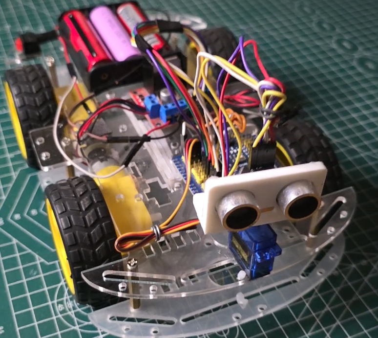
The “It Won’t Hit the Wall” Moment – Obstacle Avoiding Car with Arduino
I still remember the first time my car approached a wall, stopped, backed up, turned, and drove away – all by itself.
No remote control. No phone app. No joystick.
Just sensors, a servo, and code.
The car “saw” the wall. It made a decision. It avoided the obstacle.
That feeling? It never gets old.
This tutorial will guide you through building a completely autonomous obstacle-avoiding car using an Arduino Nano, L298N motor driver, HC-SR04 ultrasonic sensor, and an SG90 servo.
No Bluetooth. No remote control. Just pure autonomous driving.
What You’ll Build – Obstacle Avoiding Car with Arduino
| Component | What It Does |
|---|---|
| Arduino Nano | The brain – processes sensor data and controls motors |
| L298N Motor Driver | Powers the 4 motors – handles high current |
| 4WD Chassis + 4 Motors | The body – moves the car |
| HC-SR04 Ultrasonic Sensor | The eyes – measures distance to obstacles |
| SG90 Servo Motor | The neck – rotates the sensor to scan left/right |
| 3x 18650 Batteries | Power source – 11.1V total |
| L7805 Voltage Regulator | Steps down 11.1V to 5V for Arduino |
What you’ll learn:
✅ How ultrasonic sensors measure distance
✅ How to mount and control a servo for scanning
✅ Obstacle detection and avoidance logic
✅ Autonomous decision making (backup, scan, turn, resume)
✅ Power distribution for robotics projects
Complete Parts List – Obstacle Avoiding Car with Arduino
| Component | Specs | Price (USD) |
|---|---|---|
| 4WD Smart Robot Car Chassis | Includes 4 DC motors + wheels | $15-25 |
| Arduino Nano | Clone version works fine | $5-8 |
| L298N Motor Driver Module | 2A per channel, up to 12V | $3-6 |
| HC-SR04 Ultrasonic Sensor | 2cm-400cm range | $2-4 |
| SG90 Servo Motor | 9g, 180° rotation | $3-5 |
| L7805 Voltage Regulator | 5V output, up to 1.5A | $0.50-1 |
| 18650 Batteries (3x) | 3.7V each, rechargeable | $6-10 |
| Battery Holder (3x) | Series connection (11.1V) | $1-2 |
| Jumper Wires | Male-to-female, male-to-male | $3-5 |
| USB Cable | For programming | $2-4 |
Total: ~$40-70 USD
How the Ultrasonic Sensor Works – Obstacle Avoiding Car with Arduino
The HC-SR04 measures distance using sound waves – just like a bat or a dolphin.
| Pin | Function |
|---|---|
| VCC | 5V power |
| GND | Ground |
| TRIG | Trigger pin – sends out a sound pulse |
| ECHO | Echo pin – listens for the reflected sound |
How it works:
Arduino sends a 10µs HIGH pulse to TRIG
Sensor emits 8 ultrasonic bursts at 40kHz
Sound waves hit an object and bounce back
Sensor detects the echo and sets ECHO HIGH
Arduino measures the pulse duration
Distance = (Duration × Speed of Sound) / 2
Formula: Distance (cm) = (duration × 0.034) / 2
The sensor can measure from 2cm to 400cm with about 3mm accuracy.
*(Photo: HC-SR04 close-up with pins labeled – TRIG, ECHO, VCC, GND)*
How the Servo Works with the Sensor – Obstacle Avoiding Car with Arduino
The SG90 servo rotates the ultrasonic sensor to scan different directions.
| Servo Angle | Position |
|---|---|
| 0° | Full Left |
| 90° | Center (straight ahead) |
| 180° | Full Right |
Why we need a servo:
Fixed sensor can only see straight ahead
Rotating sensor can check left AND right
Car can choose the clearer path
The servo is mounted on the front of the car with the HC-SR04 attached on top. When an obstacle is detected, the car:
Stops and backs up
Rotates servo left (0°) – measures distance
Rotates servo right (180°) – measures distance
Returns servo to center (90°)
Turns toward the clearer direction
Resumes forward movement
*(Photo: Servo mounted on car with HC-SR04 attached, showing rotation angles)*
Power Distribution (Critical!)
With 3×18650 batteries in series, you get 11.1V (3.7V × 3). Here’s how to distribute it:
| Component | Voltage | Power Source |
|---|---|---|
| L298N (Motors) | 11.1V direct | Battery (via switch) |
| L7805 → Arduino 5V | 5V regulated | From 11.1V battery |
| L7805 → HC-SR04 VCC | 5V regulated | From L7805 output |
| L7805 → Servo VCC | 5V regulated | From L7805 output |
Important: Common ground is essential! Connect L298N GND, Arduino GND, L7805 GND, and battery negative together.
Complete Wiring Table
L7805 Voltage Regulator
| L7805 Pin | Connect To |
|---|---|
| Pin 1 (Input) | Battery Positive (11.1V) |
| Pin 2 (Ground) | Battery Negative |
| Pin 3 (Output) | Arduino 5V, HC-SR04 VCC, Servo VCC |
Add capacitors for stability:
0.33µF between Pin 1 and Pin 2
0.1µF between Pin 3 and Pin 2
L298N Motor Driver
| L298N Pin | Arduino Pin | Function |
|---|---|---|
| ENA | D10 | PWM – Left motor speed |
| IN1 | D9 | Left motor direction A |
| IN2 | D8 | Left motor direction B |
| IN3 | D7 | Right motor direction A |
| IN4 | D6 | Right motor direction B |
| ENB | D5 | PWM – Right motor speed |
| 12V | Battery Positive (11.1V) | Motor power |
| GND | Battery Negative & Arduino GND | Common ground |
Important: Remove the yellow jumpers from ENA and ENB! This enables PWM speed control.
HC-SR04 Ultrasonic Sensor
| HC-SR04 Pin | Arduino Pin |
|---|---|
| VCC | 5V (from L7805) |
| GND | GND |
| TRIG | D12 |
| ECHO | D13 |
SG90 Servo Motor
| Servo Wire | Arduino Pin |
|---|---|
| Brown/Black | GND |
| Red | 5V (from L7805) |
| Orange/Yellow | D3 |
4WD Motor Wiring (Parallel Connection)
For 4WD, connect motors in parallel so both left wheels turn together and both right wheels turn together:
Left Side Motors (both turn together):
Left Front Motor (+) → OUT1
Left Front Motor (-) → OUT2
Left Rear Motor (+) → same as Left Front Motor (+)
Left Rear Motor (-) → same as Left Front Motor (-)
Right Side Motors (both turn together):
Right Front Motor (+) → OUT3
Right Front Motor (-) → OUT4
Right Rear Motor (+) → same as Right Front Motor (+)
Right Rear Motor (-) → same as Right Front Motor (-)
The Complete Code – Obstacle Avoiding Car with Arduino
// Simple Obstacle Avoidance Car - Backward First, Then Scan
// Motors run at full speed only
// Complete Working Code - Do Not Modify

#include <Servo.h>

// ========== MOTOR PINS ==========
const int IN1 = 9;
const int IN2 = 8;
const int IN3 = 7;
const int IN4 = 6;

// ========== SERVO & ULTRASONIC ==========
const int SERVO_PIN = 3;
const int TRIG_PIN = 12;
const int ECHO_PIN = 13;

// ========== SETTINGS ==========
const int SAFE_DISTANCE = 30; // cm - detect obstacle
const int BACKWARD_DURATION = 150; // ms - how long to go backward
const int TURN_DURATION = 300; // ms - how long to turn
const int SCAN_DELAY = 150; // ms - delay for servo movement

// Scanning angles
const int ANGLE_LEFT = 180; // Full left
const int ANGLE_CENTER = 90; // Center
const int ANGLE_RIGHT = 0; // Full right

Servo myServo;
bool servoAtCenter = true;

void setup() {
// Motor pins
pinMode(IN1, OUTPUT);
pinMode(IN2, OUTPUT);
pinMode(IN3, OUTPUT);
pinMode(IN4, OUTPUT);

// Ultrasonic
pinMode(TRIG_PIN, OUTPUT);
pinMode(ECHO_PIN, INPUT);

// Servo
myServo.attach(SERVO_PIN);
myServo.write(ANGLE_CENTER);
delay(500);

Serial.begin(9600);

// Start moving forward
moveForward();
}

void loop() {
int distance = getDistance();

if (distance < SAFE_DISTANCE) {
// Obstacle detected - avoid it
avoidObstacle();
} else {
// Make sure servo stays at center during normal driving
if (!servoAtCenter) {
myServo.write(ANGLE_CENTER);
servoAtCenter = true;
delay(50);
}
moveForward();
}
}

// ========== MOTOR FUNCTIONS ==========

void moveForward() {
digitalWrite(IN1, HIGH);
digitalWrite(IN2, LOW);
digitalWrite(IN3, HIGH);
digitalWrite(IN4, LOW);
}

void moveBackward() {
digitalWrite(IN1, LOW);
digitalWrite(IN2, HIGH);
digitalWrite(IN3, LOW);
digitalWrite(IN4, HIGH);
}

void turnLeft() {
digitalWrite(IN1, HIGH);
digitalWrite(IN2, LOW);
digitalWrite(IN3, LOW);
digitalWrite(IN4, HIGH);
}

void turnRight() {
digitalWrite(IN1, LOW);
digitalWrite(IN2, HIGH);
digitalWrite(IN3, HIGH);
digitalWrite(IN4, LOW);
}

void stopCar() {
digitalWrite(IN1, LOW);
digitalWrite(IN2, LOW);
digitalWrite(IN3, LOW);
digitalWrite(IN4, LOW);
}

// ========== ULTRASONIC FUNCTIONS ==========

int getDistance() {
digitalWrite(TRIG_PIN, LOW);
delayMicroseconds(2);
digitalWrite(TRIG_PIN, HIGH);
delayMicroseconds(10);
digitalWrite(TRIG_PIN, LOW);

long duration = pulseIn(ECHO_PIN, HIGH, 30000);

if (duration == 0) return 999;
return duration * 0.034 / 2;
}

int scanAngle(int angle) {
myServo.write(angle);
delay(SCAN_DELAY);
return getDistance();
}

// ========== OBSTACLE AVOIDANCE LOGIC ==========

void avoidObstacle() {
// Step 1: Stop the car
stopCar();
delay(50);

// Step 2: Go BACKWARD a few steps
Serial.println("Obstacle! Moving backward...");
moveBackward();
delay(BACKWARD_DURATION);

// Step 3: Stop
stopCar();
delay(50);

// Step 4: Scan LEFT and RIGHT
Serial.println("Scanning left and right...");

int leftDist = scanAngle(ANGLE_LEFT); // Scan left first
delay(500); // Wait for servo to complete rotation

int rightDist = scanAngle(ANGLE_RIGHT); // Scan right
delay(500); // Wait for servo to complete rotation

// Step 5: Return servo to CENTER
myServo.write(ANGLE_CENTER);
servoAtCenter = true;
delay(300); // Wait for servo to return to center

// Step 6: Turn toward clearer path
Serial.print("Left: ");
Serial.print(leftDist);
Serial.print("cm | Right: ");
Serial.print(rightDist);
Serial.println("cm");

if (leftDist > rightDist) {
Serial.println("Turning LEFT");
turnLeft();
} else {
Serial.println("Turning RIGHT");
turnRight();
}

delay(TURN_DURATION);

// Step 7: Stop turning
stopCar();
delay(50);

// Step 8: Resume forward
Serial.println("Moving forward again...");
moveForward();
}
Step-by-Step Assembly – Obstacle Avoiding Car with Arduino
Step 1: Build the Chassis
Assemble the 4WD chassis kit. Mount all 4 motors and attach the wheels.
Step 2: Mount Electronics
Secure Arduino Nano, L298N, L7805, battery holder, servo, and HC-SR04 to the chassis.
Servo mounting:
Mount servo vertically on the front of the chassis
Attach a servo horn/arm
Mount HC-SR04 on top of the servo horn
Ensure the sensor can rotate freely (0° to 180°)
Step 3: Wire the Power System
Connect L7805 and L298N to the battery as shown in the wiring table. Add the switch between battery positive and the rest of the circuit.
Step 4: Wire the Control System
Connect L298N, HC-SR04, and servo to Arduino using jumper wires.
Critical check: Remove jumpers from ENA and ENB on L298N for PWM control!
Step 5: Upload Code
Connect Arduino via USB. Select Board: Arduino Nano. Upload the code.
Step 6: Power Up and Test
Turn on the switch. Place the car on the floor. Watch it drive and avoid obstacles!
How the Obstacle Avoidance Works
The car follows this decision tree:
Start → Move Forward
    ↓
Check distance straight ahead
    ↓
Distance < 45cm? → NO → Continue forward
    ↓ YES
Stop car
    ↓
Back up (150ms)
    ↓
Scan LEFT (0°)
    ↓
Scan RIGHT (180°)
    ↓
Return servo to center (90°)
    ↓
Left path clearer? → YES → Turn Left
    ↓ NO
Turn Right
    ↓
Stop turning
    ↓
Resume forward
    ↓
Repeat
Adjusting Sensitivity
You can fine-tune these values at the top of the code:
| Parameter | Default | Effect |
|---|---|---|
SAFE_DISTANCE | 45 cm | Lower = detects later, Higher = detects earlier |
BACKWARD_DURATION | 150 ms | Longer = backs up more |
TURN_DURATION | 200 ms | Longer = turns sharper |
motorSpeed | 200 | Lower = slower, Higher = faster |
turnSpeed | 180 | Lower = slower turn, Higher = faster turn |
Recommendations for high speed: Increase SAFE_DISTANCE to 60-70cm so the car detects obstacles earlier.
Troubleshooting
| Problem | Likely Cause | Fix |
|---|---|---|
| Car doesn’t move | ENA/ENB jumpers still on | Remove the jumper caps |
| Car moves opposite direction | Motor polarity reversed | Swap motor wires or swap HIGH/LOW in code |
| One side doesn’t move | Loose connection on that channel | Check IN pins and OUT terminals |
| Servo doesn’t rotate | Wrong pin or power issue | Check D3 connection, ensure 5V supply |
| Sensor gives false readings | Noise on power lines | Add 100µF capacitor across 5V/GND |
| Car backs into obstacles | BACKWARD_DURATION too long | Reduce to 100-150ms |
| Car turns too much | TURN_DURATION too long | Reduce to 150-200ms |
| Car doesn’t see obstacles | Sensor mounted incorrectly | Ensure sensor points forward at 90° |
Make It Your Own (Upgrades)
| Upgrade | Difficulty | What You’ll Need |
|---|---|---|
| Speed control via pot | ⭐ Easy | Potentiometer + analogRead |
| LED headlights | ⭐ Easy | White LEDs + resistors |
| Battery voltage monitor | ⭐⭐ Medium | Voltage divider circuit |
| LCD display | ⭐⭐ Medium | 16×2 I2C LCD |
| ESP32 version | ⭐⭐ Medium | ESP32 board (adds WiFi/BLE) |
| Line following mode | ⭐⭐⭐ Hard | IR sensors |
What You Learned
| Concept | Why It Matters |
|---|---|
| Ultrasonic distance measurement | Non-contact object detection |
| Servo control for scanning | Rotating sensors increase field of view |
| Obstacle avoidance logic | Autonomous decision making |
| PWM speed control | Variable motor speed |
| Power distribution | Separate high-current and logic circuits |
🎥 Watch the Complete Video Tutorial
See the obstacle-avoiding car in action – assembly, wiring, code explanation, and live demo:
📺 Build an Autonomous Obstacle Avoiding Car with Arduino
👉 Don’t forget to Subscribe to Roborear on YouTube for more robotics projects every week!
Your Turn
This project taught me that autonomous robots don’t need expensive sensors or complex algorithms. A $2 ultrasonic sensor, a $3 servo, and some simple logic are enough to create a car that navigates its environment.
Now go build yours. Watch it explore. See how it handles corners, walls, and obstacles.
And when it gets stuck? Tweak the values. Adjust the timing. Make it smarter.
That’s how you learn.
FAQs
1. Why does my car back up first when it sees an obstacle? Why not just turn immediately?
Backing up first creates space for the car to maneuver. If the car tries to turn immediately, it might scrape against the obstacle or get stuck. By reversing 150ms first, the car creates a small gap, then scans left and right, then turns into the clearer path.
Think of it like parallel parking – you need to back up before you can turn. Without the backup step, the car would pivot directly into the obstacle, potentially damaging the sensor or getting wedged.
The backup duration (150ms) is adjustable. For tight spaces, reduce it to 100ms. For open areas, increase to 200-250ms for more clearance.
2. Why do I need to remove the jumpers from ENA and ENB on the L298N?
The jumpers on ENA (Enable A) and ENB (Enable B) connect these pins directly to 5V, which forces the motors to run at full speed. When you want speed control (PWM), you must remove these jumpers and connect the pins to Arduino PWM-capable pins (D10 and D5).
With jumpers removed, analogWrite(ENA, value) sends a PWM signal that controls motor speed from 0 to 255. With jumpers on, analogWrite() has no effect – motors run at full speed regardless of your code.
The jumpers are a convenience feature for simple ON/OFF control. For obstacle avoidance with variable speed, you need them removed.
If you forget to remove the jumpers, the car may still work but speed control won’t function – the car will always move at maximum speed.
3. My car spins in circles instead of avoiding obstacles. What's wrong?
This usually means one of two things:
Problem 1: Wrong turn logic – Your left and right wheels are moving in opposite directions during a turn, which spins the car in place. Check your turnLeft() and turnRight() functions. A proper pivot turn should have one side forward, one side backward.
Problem 2: Turn duration too long – If TURN_DURATION is set too high (e.g., 500ms instead of 200ms), the car will overshoot and may spin. Reduce the turn duration to 150-250ms.
Problem 3: One motor not working – If only one side of motors is receiving power, the car will spin. Check your L298N connections, especially IN3/IN4 and ENB. Also verify the ENA/ENB jumpers are removed.
Quick test: Run just the turnLeft() function for 500ms in setup() and observe which wheels spin. Left motors should go backward, right motors forward. If not, swap the motor connections or fix your code logic.

